Introduction to Programming Infiniband RDMA
Table of Contents
This post explains the basic of RDMA programming. There are many examples and posts regarding this, however, I personally could not find enough explanations for the examples. It was hard to understand how it works, and here I summarize what I got.
Backgrounds #
Channel Adapter (CA) #
Channel adapter refers an end node in the infiniband network. It is equivalent of Ethernet network interface card (NIC), but with more features regarding Infiniband and RDMA 1.
Queue Pair (QP), a set of a Send Queue (SQ), a Receive Queue (RQ), and a Completion Queue (CQ) #
HCAs communicate with each other using work queues. Three types of the queues are: (1) send queue (SQ), (2) receive queue (RQ), and (3) a completion queue. SQ and RQ are always grouped and managed as a queue pair (QP).
We can post a work request (WR) by generating a work queue entry (WRE) into the work queue, e.g. (1) posting a send work request into the SQ to send some data to a remote node, (2) posting a receive work request into the RQ to receive data from a remote node, etc. Posted work requests are directly handled by hardware (HCA) 3 4. Once a request is completed, the hardware posts a Work Completion (WC) into a completion queue (CQ). Programming Interface provides flexibility that we can specify distinct completion queues to the SQ and the RQ, or use one CQ for the entire QP.
In short, programming RDMA program is roughly easy: generate a QP and a CQ (and other required data structures for this operation, which will be introduced later), connect the QP to the remote node, and generate a work request (WR) and post it into the QP.
Then the HCA transfers your orders to the connected counterpart.
libibverbs APIs #
libibverbs library provides high level userspace APIs to use Infiniband HCAs 3 4.
With the APIs, the program runs as the following simplified description:
- Create an Infiniband context (
struct ibv_context* ibv_open_device()) - Create a protection domain (
struct ibv_pd* ibv_alloc_pd()) - Create a completion queue (
struct ibv_cq* ibv_create_cq()) - Create a queue pair (
struct ibv_qp* ibv_create_qp()) - Exchange identifier information to establish connection
- Change the queue pair state (
ibv_modify_qp()): change the state of the queue pair from RESET to INIT, RTR (Ready to Receive), and finally RTS (Ready to Send) 5 - Register a memory region (
ibv_reg_mr()) - Exchange memory region information to handle operations
- Perform data communication
In 3, [4], and many example codes, 6: memory region registration is illustrated as a part of initialization (somewhere between step 2~6). However, there is no problem for lazy registration and memory regions can dynamically be registered and deregistered at any time before posting a work request (after step 6).
More specifically, I want to divide the program flow to two groups: step 1~6 as an initialization phase, step 7~9 as a runtime phase. We will discuss more about this in step 7.
Note that 4 listed and grouped related functions well. I only show how the sequence of those function calls should be.
1. Create an Infiniband context #
Open the HCA and generate a userspace device context.
struct ibv_context* createContext(const std::string& device_name) {
  /* There is no way to directly open the device with its name; we should get the list of devices first. */
  struct ibv_context* context = nullptr;
  int num_devices;
  struct ibv_device** device_list = ibv_get_device_list(&num_devices);
  for (int i = 0; i < num_devices; i++){
    /* match device name. open the device and return it */
    if (device_name.compare(ibv_get_device_name(device_list[i])) == 0) {
      context = ibv_open_device(device_list[i]);
      break;
    }
  }

  /* it is important to free the device list; otherwise memory will be leaked. */
  ibv_free_device_list(device_list);
  if (context == nullptr) {
    std::cerr << "Unable to find the device " << device_name << std::endl;
  }
  return context;
}
2. Create a protection domain #
Literally create a protection domain, protecting resources from arbitrary accesses from the remote. Components that can be registered to a protection domain is
- memory regions (MRs)
- memory windows (MWs)
- queue pairs (QPs)
- shared receive queues (SRQs)
- address handles (AH) 1.
Note that completion queues (CQs) are not in protection domains 4.
e.g. Registering a memory region requires a pointer to a protection domain, indicating that this memory region will be registered to the protection domain.
struct ibv_mr *ibv_reg_mr(struct ibv_pd *pd, ...);[manual page]
As explained, memory regions are not necessarily to be registered right after creating a protection domain. As queue pairs are also registered to the protection domain, creating a protection domain is in an early initialization step.
struct ibv_context* context = createContext(/* device name */);
struct ibv_pd* protection_domain = ibv_alloc_pd(context);
3. Create a completion queue #
It is a prerequisite step to create a queue pair, like step 2.
struct ibv_context* context = createContext(/* device name */);

int cq_size = 0x10;
struct ibv_cq* completion_queue = ibv_create_cq(context, cq_size, nullptr, nullptr, 0);
Function signature for
ibv_create_cqis:struct ibv_cq *ibv_create_cq(struct ibv_context *context, int cqe, void *cq_context, struct ibv_comp_channel *channel, int comp_vector);. [manual page]All examples that I saw pass
nullptrto bothcq_contextandchanneland worked well, so I do not understand what they exactly do.
4. Create a queue pair #
Now we are ready to create a queue pair.
struct ibv_qp* createQueuePair(struct ibv_pd* pd, struct ibv_pd* pd, struct ibv_cq* cq) {
  struct ibv_qp_init_attr queue_pair_init_attr;
  memset(&queue_pair_init_attr, 0, sizeof(queue_pair_init_attr));
  queue_pair_init_attr.qp_type = IBV_QPT_RC;
  queue_pair_init_attr.sq_sig_all = 1;       // if not set 0, all work requests submitted to SQ will always generate a Work Completion.
  queue_pair_init_attr.send_cq = cq;         // completion queue can be shared or you can use distinct completion queues.
  queue_pair_init_attr.recv_cq = cq;         // completion queue can be shared or you can use distinct completion queues.
  queue_pair_init_attr.cap.max_send_wr = 1;  // increase if you want to keep more send work requests in the SQ.
  queue_pair_init_attr.cap.max_recv_wr = 1;  // increase if you want to keep more receive work requests in the RQ.
  queue_pair_init_attr.cap.max_send_sge = 1; // increase if you allow send work requests to have multiple scatter gather entry (SGE).
  queue_pair_init_attr.cap.max_recv_sge = 1; // increase if you allow receive work requests to have multiple scatter gather entry (SGE).

  return ibv_create_qp(pd, &queue_pair_init_attr);
}
qp_typeindiciates the type of this queue pair. There are three types of queue pairs: (1) Reliable Connection (RC), (2) Unreliable Connection (UC), and (3) Unreliable Datagram (UD). Refer to Chapter 2.2 Transport Modes in 1 for more details.
5. Exchange identifier information to establish connection and 6. change the queue pair state #
Right after created, the queue pair has a state RESET. With this state the queue pair does not work. We have to establish queue pair connection with another queue pair to make it work.
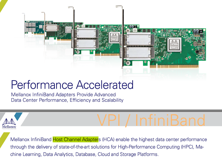
The queue pair state machine diagram is as follows.
In order to have a working queue pair, we need to modify the queue pair’s state to either RTR (Ready to Receive) or RTS(Ready to Send), by using ibv_modfiy_qp().
int ibv_modify_qp(struct ibv_qp *qp, struct ibv_qp_attr *attr, int attr_mask);[manual page]
Following the state machine diagram, we first should change the state to INIT.
bool changeQueuePairStateToInit(struct ibv_qp* queue_pair) {
  struct ibv_qp_attr init_attr;
  memset(&init_attr, 0, sizeof(init_attr));
  init_attr.qp_state = ibv_qp_state::IBV_QPS_INIT;
  init_attr.port_num = device_port_;
  init_attr.pkey_index = 0;
  init_attr.qp_access_flags = IBV_ACCESS_LOCAL_WRITE | IBV_ACCESS_REMOTE_READ | IBV_ACCESS_REMOTE_WRITE;

  return ibv_modify_qp(queue_pair, &init_attr, IBV_QP_STATE | IBV_QP_PKEY_INDEX | IBV_QP_PORT | IBV_QP_ACCESS_FLAGS) == 0 ? true : false;
}
Then change the state to RTR.
bool changeQueuePairStateToRTR(struct ibv_qp* queue_pair, int ib_port, uint32_t destination_qp_number, uint16_t destination_local_id) {
  struct ibv_qp_attr rtr_attr;
  memset(&rtr_attr, 0, sizeof(rtr_attr));
  rtr_attr.qp_state = ibv_qp_state::IBV_QPS_RTR;
  rtr_attr.path_mtu = ibv_mtu::IBV_MTU_1024;
  rtr_attr.rq_psn = 0;
  rtr_attr.max_dest_rd_atomic = 1;
  rtr_attr.min_rnr_timer = 0x12;
  rtr_attr.ah_attr.is_global = 0;
  rtr_attr.ah_attr.sl = 0;
  rtr_attr.ah_attr.src_path_bits = 0;
  rtr_attr.ah_attr.port_num = ib_port;

  rtr_attr.dest_qp_num = destination_qp_number;
  rtr_attr.ah_attr.dlid = destination_local_id;

  return ibv_modify_qp(queue_pair, &rtr_attr, IBV_QP_STATE | IBV_QP_AV | IBV_QP_PATH_MTU | IBV_QP_DEST_QPN | IBV_QP_RQ_PSN | IBV_QP_MAX_DEST_RD_ATOMIC | IBV_QP_MIN_RNR_TIMER) == 0 ? true : false;
}
Note that several arguments are taken.
ib_port #
ib_port is a port number that this queue pair uses in the host. You can easily see how many ports the device supports and their numbers with ibstat:
$ ibstat
CA 'mlx5_0'
        CA type: MT4115
        Number of ports: 1
        Firmware version: 12.23.1020
        Hardware version: 0
        Node GUID: /* omitted */
        System image GUID: /* omitted */
        Port 1:
                State: Active
                Physical state: LinkUp
                Rate: 56
                Base lid: 13
                LMC: 0
                SM lid: 9
                Capability mask: /* omitted */
                Port GUID: /* omitted */
                Link layer: InfiniBand
Install
infiniband-diagsif you want to useibstatcommand.
My CA has one port and its number is 1. You can manually pass this information when you launch a program.
destination_qp_number and destination_local_id #
For the queue pair to connect the other queue pair and be ready to receive, it has to know information about the peer QP.
destination_qp_number and destination_local_id are the ones.
destination_local_id: it works as a local identifier in the subnet where the HCA is assigned to. this is assigned to each ports by the subnet manager and unique within its subnet. For communications over the subnet, we can use GID (Global ID), but it will not be covered in this post. To find a local id, you can use the following function.
uint16_t getLocalId(struct ibv_context* context, int ib_port) {
  ibv_port_attr port_attr;
  ibv_query_port(context, ib_port, &port_attr);
  return port_attr.lid;
}
destination_qp_number: a queue pair is at least created, so the unique identifier for the queue pair is already assigned.
uint32_t getQueuePairNumber(struct ibv_qp* qp) {
  return qp->qp_num;
}
Note that these return its local information, not a destination information (information of the opposite node). It means these functions must be called in each side and they exchange information to know each other’s destination information.
For this purpose, all examples that I referred use a TCP socket. Before processing RDMA operations, a server and a client establish a TCP connection and exchange their local ID and QP number. This is why step 5 includes exchange identifier information.
The TCP connection is also used in step 8, to let the counterpart know about its memory regions.
After calling changeQueuePairStateToRTR(), the queue pair is not able to receive data by posting receive work requests. If you want to make it able to send data, the state should be further changed to RTS.
bool changeQueuePairStateToRTS(struct ibv_qp* queue_pair) {
  struct ibv_qp_attr rts_attr;
  memset(&rts_attr, 0, sizeof(rts_attr));
  rts_attr.qp_state = ibv_qp_state::IBV_QPS_RTS;
  rts_attr.timeout = 0x12;
  rts_attr.retry_cnt = 7;
  rts_attr.rnr_retry = 7;
  rts_attr.sq_psn = 0;
  rts_attr.max_rd_atomic = 1;

  return ibv_modify_qp(queue_pair, &init_attr, IBV_QP_STATE | IBV_QP_TIMEOUT | IBV_QP_RETRY_CNT | IBV_QP_RNR_RETRY | IBV_QP_SQ_PSN | IBV_QP_MAX_QP_RD_ATOMIC) == 0 ? true : false;
}
As peer information is already stored at RTR step, changing the state to RTS does not require any further peer information.
7. Register a memory region #
Until step 6, it is an initialization phase. After step 6 the queue pair is able to communicate each other; a posted work request is forwarded to the opposite node, the HCA of which will consume it. Of course, this will be rejected due to permission error since there is no memory regions registered; work requests are unable to read or write anything from or to any space of the peer node.
In other words, it is okay to register memory regions before the peer node posts a work request.
Before discussing it further, let us dig into types of operations that Infiniband supports (Refer to *Section 2.1 in 1):
- Send/Send with Immediate: [RTS state required] send data to a remote QP’s receive queue.
- Receive: [RTR/RTS state required] corresponding operation to a send operation; the host is notified when a data buffer has been received.
- RDMA Read: [RTS state required] read data from the remote memory. The remote side is not aware of this operation being done.
- RDMA Write/RDMA Write with Immediate: [RTS state required] write data to the remote memory. The remote side is not aware of this operation being done.
- Atomic Fetch and Swap / Atomic Compare and Swap: Refer to *Section 2.1.4 in 1
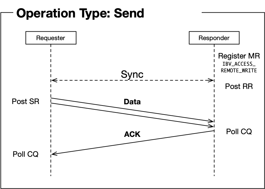
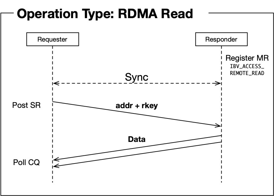
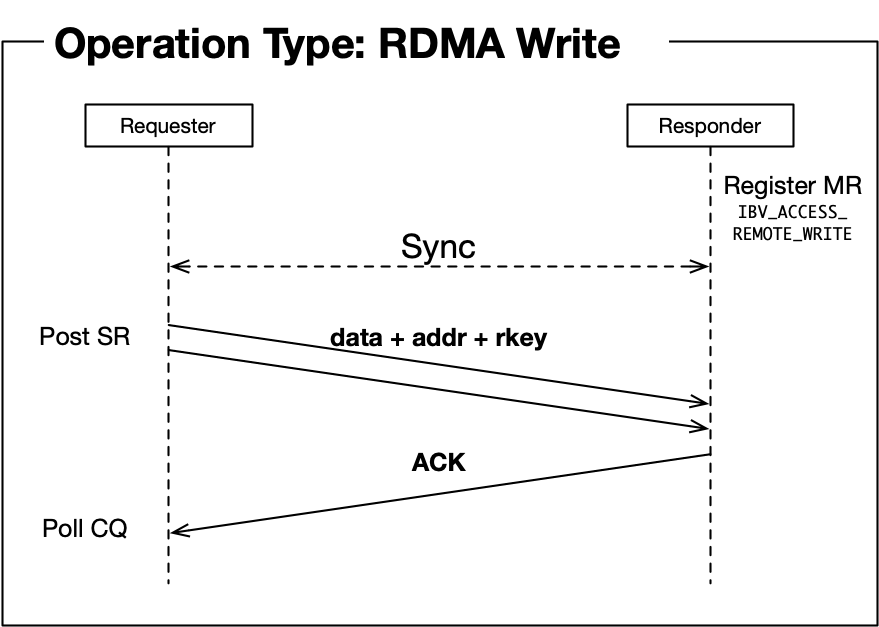
- Those sequence diagrams are refined images illustrated in 4.
Personally thinking, the main reason memory region registration is mostly in initialization phase is due to RDMA operations. Different from receive operation, where the remote side actively post a receive work request so that it is able to decide the moment that a memory region is registered (just before posting a receive work request), RDMA read and RDMA write can be done without any operations in the remote node, requiring the memory region to be registered in advance.
Again, in operation, there is no problem initializing a queue pair without registering memory regions. It is a runtime problem that the HCA cannot read or write data from or to the remote node’s memory.
To register a memory region, use ibv_reg_mr().
struct ibv_mr* registerMemoryRegion(struct ibv_pd* pd, void* buffer, size_t size) {
  return ibv_reg_mr(pd, buffer, size, IBV_ACCESS_LOCAL_WRITE | IBV_ACCESS_REMOTE_READ | IBV_ACCESS_REMOTE_WRITE);
}
Note that we can specify the range of remote access in this memory region. Five flags are provided [manual page]:
IBV_ACCESS_LOCAL_WRITE: enable local write accessIBV_ACCESS_REMOTE_WRITE: enable remote write accessIBV_ACCESS_REMOTE_READ: enable remote read accessIBV_ACCESS_REMOTE_ATOMIC: enable remote atomic operation accessIBV_ACCESS_MW_BIND: enable memory window bindingIf
IBV_ACCESS_REMOTE_WRITEorIBV_ACCESS_REMOTE_ATOMICis set, thenIBV_ACCESS_LOCAL_WRITEmust be set too.
8. Exchange memory region information to handle operations and 9. Perform data communication #
Memory region is a required data for communication, it also has to be sent through a TCP channel.
Here is a data structure of a registered memory region that is returned by calling ibv_reg_mr():
struct ibv_mr {
	struct ibv_context     *context;
	struct ibv_pd	       *pd;
	void		       *addr;
	size_t			length;
	uint32_t		handle;
	uint32_t		lkey;
	uint32_t		rkey;
};
What we actually need for data transfer are:
- address
- length
- lkey (local key)
- rkey (remote key)
Other data are not necessary, but simply sending the whole data as a byte stream would be enough.
With the memory region information, you can use RDMA between two devices with ibv_post_send() and ibv_post_recv().
Send/Recv #
Send and Recv are a pair of operations; they need each other for proper operation.
bool postReceiveRequest(const std::vector<struct ibv_mr*>& sge) {
  struct ibv_recv_wr receive_wr, *bad_wr = nullptr;
  memset(&receive_wr, 0, sizeof(receive_wr));

  // RDMA supports scatter-gather I/O.
  // For a RECV operation, it works as scatter; received data will be scattered into several registered MR.
  struct ibv_sge* receive_sge = calloc(sizeof(struct ibv_sge), sge.size());
  for (int i = 0; i < sge.size(); i++) {
    receive_sge[i].addr = (uintptr_t) sge[i].addr;
    receive_sge[i].length = sge[i].length;
    receive_sge[i].lkey = sge[i].lkey;
  }

  receive_wr.sg_list = receive_sge;
  receive_wr.num_sge = sge.size();
  // will be used for identification.
  // When a request fail, ibv_poll_cq() returns a work completion (struct ibv_wc) with the specified wr_id.
  // If the wr_id is 100, we can easily find out that this RECV request failed.
  receive_wr.wr_id = 100;
  // You can chain several receive requests to reduce software footprint, hnece to improve latency.
  receive_wr.next = nullptr;

  // If posting fails, the address of the failed WR among the chained WRs is stored in bad_wr.
  auto result = ibv_post_recv(queue_pair_, &receive_wr, &bad_wr);
  free(receive_sge);

  return result == 0 ? true : false;
}
bool postSendRequest(const std::vector<struct ibv_mr*>& sge) {
  struct ibv_send_wr send_wr, *bad_wr = nullptr;
  memset(&send_wr, 0, sizeof(send_wr));

  struct ibv_sge* send_sge = calloc(sizeof(struct ibv_sge), sge.size());
  for (int i = 0; i < sge.size(); i++) {
    send_sge[i].addr = (uintptr_t) sge[i].addr;
    send_sge[i].length = sge[i].length;
    send_sge[i].lkey = sge[i].lkey;
  }

  send_wr.sg_list = send_sge;
  send_wr.num_sge = sge.size();
  send_wr.wr_id = 200;

  // All WRs that are posted into Send Queue (SQ) are posted via ibv_send_wr.
  // You should specify the opcode so that which operation you want to do.
  send_wr.opcode = IBV_WR_SEND;
  // With IBV_SEND_SIGNALED flag, the hardware creates a work completion (wc) entry into the completion queue connected to the send queue.
  // You can wait with ibv_poll_cq() call until it finishes its operation.
  send_wr.send_flags = IBV_SEND_SIGNALED;
  send_wr.next = nullptr;

  auto result = ibv_post_send(queue_pair_, &send_wr, &bad_wr);
  free(send_sge);

  return result == 0 ? true : false;
}
RDMA READ / RDMA WRITE #
Likewise, you can send RDMA WRITE or RDMA READ request with postSendRequest(), but with different opcodes:
- RDMA READ:
IBV_WR_RDMA_READ - RDMA WRITE:
IBV_WR_RDMA_WRITERefer to the [manual] for SEND WR opcode details.
For RDMA READ/WRITE, you have to specify additional arguments in ibv_send_wr. RDMA READ, for example:
bool postRDMAReadRequest(const std::vector<struct ibv_mr*>& sge, struct ibv_mr* peer_memory_region) {
  struct ibv_send_wr rdma_wr, ...;
  rdma_wr.wr.rdma.remote_addr = peer_memory_region->addr;
  rdma_wr.wr.rdma.rkey = peer_memory_region->rkey;
  rdma.wr.opcode = IBV_WR_RDMA_READ;

  // All the others same
}
This function postRDMAReadRequest reads data from peer_memory_region in the remote peer node and scatter it into ibv_mrs in sge.
Poll Completion #
When the device completes operations, it creates corresponding work completion (wc) entries into the connected completion queue (You specify the completion queue when creating a queue pair. Refer Section 4).
Basically, we can poll the completion queue to check whether works are done.
Polling is not the only way of work completion detection. RDMA provides a notification mechanism, however, polling usually is faster (low latency) for detection, as notification requires several context switches, process scheduling, etc.
For more detials, refer to 7. This post will not cover this and only tells about polling.
We use ibv_poll_cq to poll a completion queue. It is a busy poll, so it consumes a CPU core, but provides lower latency.
bool pollCompletion(struct ibv_cq* cq) {
  struct ibv_wc wc;
  int result;

  do {
    // ibv_poll_cq returns the number of WCs that are newly completed,
    // If it is 0, it means no new work completion is received.
    // Here, the second argument specifies how many WCs the poll should check,
    // however, giving more than 1 incurs stack smashing detection with g++8 compilation.
    result = ibv_poll_cq(cq, 1, &wc);
  } while (result == 0);

  if (result > 0 && wc.status == ibv_wc_status::IBV_WC_SUCCESS) {
    // success
    return true;
  }

  // You can identify which WR failed with wc.wr_id.
  printf("Poll failed with status %s (work request ID: %llu)\n", ibv_wc_status_str(wc.status), wc.wr_id);
  return false;
}
ibv_poll_cq returns the number of WCs. As we specify it has to wait at most one WC, the result must be either 0, 1, or negative if error occured.

